OneWire Data Source
The OneWire data source connects Mango to Dallas/Maxim 1-Wire devices through a USB or serial adapter. 1-Wire is a low-speed bus protocol that uses a single data line (plus ground) to communicate with sensors and other peripherals. It is widely used in temperature monitoring, environmental sensing, and facility management applications where large numbers of inexpensive sensors are deployed along long cable runs.
Each 1-Wire device has a globally unique 64-bit ROM address burned in at the factory, which means devices can be auto-discovered on the bus without manual addressing. Mango reads values from these devices by polling the adapter at a configurable interval.
Overview
| Property | Value |
|---|---|
| Module | mangoAutomation-OneWire |
| Protocol | 1-Wire (Dallas Semiconductor / Maxim Integrated) |
| Direction | Polling |
| Typical Use | Temperature monitoring with DS18B20/DS18S20 sensors, humidity sensing, analog-to-digital conversion, event counting |
The 1-Wire protocol supports many device families, but the most common deployment is temperature monitoring using the DS18B20 digital thermometer. A single bus adapter can communicate with dozens of devices daisy-chained along cable runs of up to 300 meters (with proper cabling and pull-up resistors). Mango discovers all devices on the bus automatically and presents them for point configuration.
Common deployment scenarios include:
- Server room monitoring -- rows of DS18B20 sensors along racks reporting inlet and exhaust temperatures.
- Cold chain logistics -- temperature logging in refrigerated storage and transport.
- Environmental monitoring -- combined temperature and humidity sensors (e.g., DS2438-based humidity boards) in greenhouses, warehouses, or data centers.
- Utility metering -- pulse-counting devices (DS2423) connected to water or gas meters.
Prerequisites
Before you begin, make sure you have:
- The
mangoAutomation-OneWiremodule installed on your Mango instance.- A supported 1-Wire USB adapter (e.g., Maxim DS9490R) or serial adapter (e.g., DS9097U) connected to the Mango host.
- The appropriate native drivers installed for your adapter and operating system.
- One or more 1-Wire devices wired to the adapter bus with proper pull-up resistors and cabling.
- Physical access to verify device wiring if this is a first-time setup.
Adapter driver notes
On Linux, the DS9490R USB adapter requires the ds2490 kernel module and the OWFS (One-Wire File System) libraries. Install the owfs package from your distribution's package manager, or compile from source. Verify the adapter is recognized:
lsusb | grep -i maxim
# Should show: Maxim Integrated Products DS9490R 1-Wire adapter
On Windows, install the Maxim 1-Wire Drivers package, which includes the 1-Wire API COM/DCOM server. After installation, verify the adapter appears in Device Manager under "1-Wire Bus Host Adapters."
Data source configuration
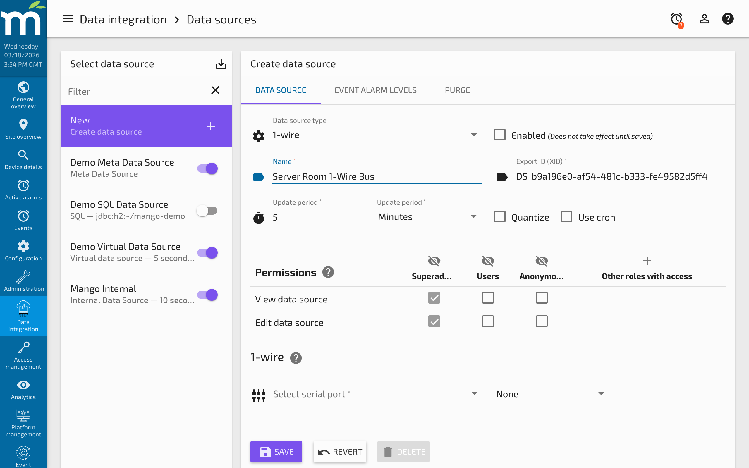
Creating the data source
- Navigate to Data Sources in the Mango menu.
- Click New and select OneWire from the data source type list.
- Enter a descriptive Name (e.g., "Server Room 1-Wire Bus").
- Configure the connection and polling settings described below.
- Click Save to create the data source.
Connection settings
| Parameter | Type | Default | Description |
|---|---|---|---|
commPortId | String | "" | The serial/COM port the 1-Wire adapter is connected to. Specify the port identifier (e.g., COM3 on Windows, /dev/ttyUSB0 on Linux). |
Polling settings
| Parameter | Type | Default | Description |
|---|---|---|---|
updatePeriodType | Enum | MINUTES | Time unit for the polling interval. Options: SECONDS, MINUTES, HOURS. |
updatePeriods | Integer | 5 | Number of time units between polls. Temperature sensors require approximately 750 ms per conversion, so very short intervals may not improve accuracy on large bus networks. |
quantize | Boolean | false | When enabled, aligns poll times to period boundaries. |
rescanPeriodType | Enum | NONE | How often to re-scan the bus for newly connected devices. Options: NONE, SECONDS, MINUTES, HOURS. Defaults to NONE (no automatic re-scanning). |
rescanPeriods | Integer | 1 | Number of time units between automatic re-scans (only applies when rescanPeriodType is not NONE). |
Device discovery
After saving and enabling the data source, Mango scans the 1-Wire bus and discovers all connected devices. Each device is identified by its 64-bit ROM address (displayed in hexadecimal, e.g., 28-00000A1B2C3D). The first two hex digits indicate the device family:
| Family Code | Device Type | Example Devices |
|---|---|---|
10 | Temperature sensor | DS18S20, DS1920 |
28 | Temperature sensor | DS18B20 (most common) |
26 | Smart battery / voltage | DS2438 (often used in humidity boards) |
1D | Counter | DS2423 (pulse counting for meters) |
20 | A/D converter | DS2450 (4-channel analog to digital) |
12 | Dual switch | DS2406 (digital I/O) |
29 | 8-channel switch | DS2408 (8-bit digital I/O) |
Click Discover devices to refresh the list of detected devices after adding or removing hardware from the bus.
Point configuration
Creating points
- With the OneWire data source open, navigate to the Points section.
- Click Add point or select a discovered device from the device list.
- Configure the device-specific settings described below.
- Click Save to add the point.
Point settings
| Parameter | Type | Default | Description |
|---|---|---|---|
address | String | "" | The 64-bit ROM address of the 1-Wire device (e.g., 28-00000A1B2C3D). Selected from the discovered devices list or entered manually. |
attributeType | Enum | Varies | The device attribute to read: TEMPERATURE, HUMIDITY, AD_VOLTAGE, LATCH_STATE, WIPER_POSITION, or COUNTER. Available attributes depend on the device family (see below). |
index | Integer | 0 | The channel/index for attributes that support multiple channels (AD_VOLTAGE, LATCH_STATE, WIPER_POSITION, COUNTER). For example, index = 1 for the second AD channel or counter B. |
Attributes by device type
Temperature sensors (DS18B20, DS18S20):
| Attribute | Data Type | Unit | Description |
|---|---|---|---|
temperature | Numeric | Celsius | The current temperature reading from the sensor. |
Voltage / humidity boards (DS2438):
| Attribute | Data Type | Unit | Description |
|---|---|---|---|
temperature | Numeric | Celsius | On-board temperature reading. |
voltage_VAD | Numeric | Volts | General-purpose A/D voltage reading (VAD pin). Used by humidity boards for the humidity sensor element. |
voltage_VDD | Numeric | Volts | Supply voltage reading (VDD pin). Useful for monitoring bus power levels. |
humidity | Numeric | %RH | Calculated relative humidity (available when a supported humidity board is detected). |
Counter devices (DS2423):
| Attribute | Data Type | Unit | Description |
|---|---|---|---|
counter_A | Numeric | Count | Cumulative pulse count on counter input A. |
counter_B | Numeric | Count | Cumulative pulse count on counter input B. |
A/D converter (DS2450):
| Attribute | Data Type | Unit | Description |
|---|---|---|---|
channel_A | Numeric | Volts | Analog voltage on channel A (0-5.12V range). |
channel_B | Numeric | Volts | Analog voltage on channel B. |
channel_C | Numeric | Volts | Analog voltage on channel C. |
channel_D | Numeric | Volts | Analog voltage on channel D. |
Switch devices (DS2406, DS2408):
| Attribute | Data Type | Description |
|---|---|---|
switch_0 through switch_N | Binary | The state of each I/O channel (on/off). DS2406 has 2 channels; DS2408 has 8 channels. |
Examples
Example 1: Basic temperature monitoring
Deploy three DS18B20 sensors monitoring server rack inlet, middle, and exhaust temperatures.
- Connect the DS9490R USB adapter to the Mango server.
- Wire the three DS18B20 sensors to the adapter using Cat5e cable with pin 1 (GND), pin 2 (data), and pin 3 (VCC/parasitic power).
- Create a OneWire data source with a 30-second polling interval.
- Click Discover devices -- three devices with family code
28appear. - Create three data points, one per device, each reading the
temperatureattribute at 12-bit resolution. - Assign descriptive point names: "Rack A Inlet", "Rack A Middle", "Rack A Exhaust".
The points now report temperature values in Celsius every 30 seconds. Use Mango's built-in unit conversion to display values in Fahrenheit if needed.
Example 2: Humidity monitoring with DS2438
A DS2438-based humidity board (such as the HobbyBoards humidity sensor) provides both temperature and relative humidity.
- Wire the humidity board to the 1-Wire bus.
- After discovery, the device appears with family code
26. - Create two points: one for
temperatureand one forhumidity. - The humidity reading is derived from the raw VAD voltage using the calibration curve built into the module.
Troubleshooting
| Symptom | Cause | Solution |
|---|---|---|
| "Adapter not detected" or no adapter listed | USB adapter not recognized by the OS, missing drivers | Verify the adapter appears in lsusb (Linux) or Device Manager (Windows). Install OWFS libraries or Maxim drivers. |
| Discovery returns no devices | Wiring fault, missing pull-up resistor, bus too long without active pull-up | Check data line wiring. Ensure a 4.7k ohm pull-up resistor is connected between data and VCC. For runs over 100m, use an active pull-up or hub. |
| Intermittent read errors or CRC errors | Electrical noise, inadequate grounding, excessive bus length | Use shielded cable. Reduce bus length or add 1-Wire hubs. Verify all connections are solid (no loose crimps). |
| Temperature reads 85.0 C constantly | Sensor returning power-on reset value; conversion not completing | Increase polling interval to allow full 750 ms conversion time. Check that VCC is provided (parasitic power may be insufficient for long runs). |
| Temperature reads -127.0 C | Device disconnected or address mismatch | Verify the device is physically connected. Re-run device discovery to refresh addresses. |
| Slow polling on large bus | Many devices each requiring 750 ms conversion | Reduce resolution to 9-bit or 10-bit for faster conversions, or increase the polling interval to accommodate all devices. |
| Counter values not incrementing | Wrong counter channel, or pulse signal not meeting threshold | Verify the correct counter channel (A or B). Ensure pulse signal meets the DS2423 input specifications (minimum 1 microsecond pulse width). |
Related Pages
- Data Sources Overview — General data source and data point concepts
- Serial Data Source — General-purpose serial communication for devices with custom protocols
- M-Bus Data Source — Another protocol for reading utility meters and environmental sensors
- Data Source Performance — Tuning poll intervals for bus networks with many devices